
Classical Fieldprobing
Classical fieldprobing, VSWR method, is the sampling of the field distribution in the quiet zone often parallel to the propagating direction of the plane wave. From the measurement the chamber reflectivity can be calculated which is a basic quality parameter for the chamber performance. However for an intuitive look on the chamber performance using a transversal measurement of the quiet zone is often more explanative. For the measurement of the quiet zone performance of the CATR measurement chamber at the institute, which has a diameter of 1.2 meter, a fieldprobing setup has been built with a maximum displacement of 1.4 meters, covering the entire quiet zone. Fig. 1 shows on the left-hand side the fieldprobing setup mounted vertically on top of the standard roll-over-azimuth AUT tower looking from the direction of the CATR reflector. On the right-hand side the feed setup can be seen.
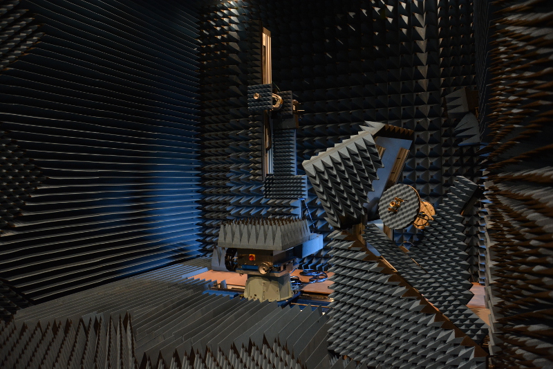
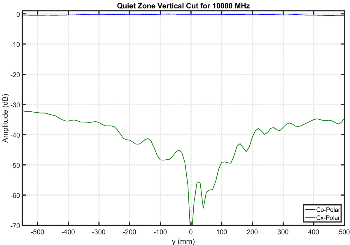
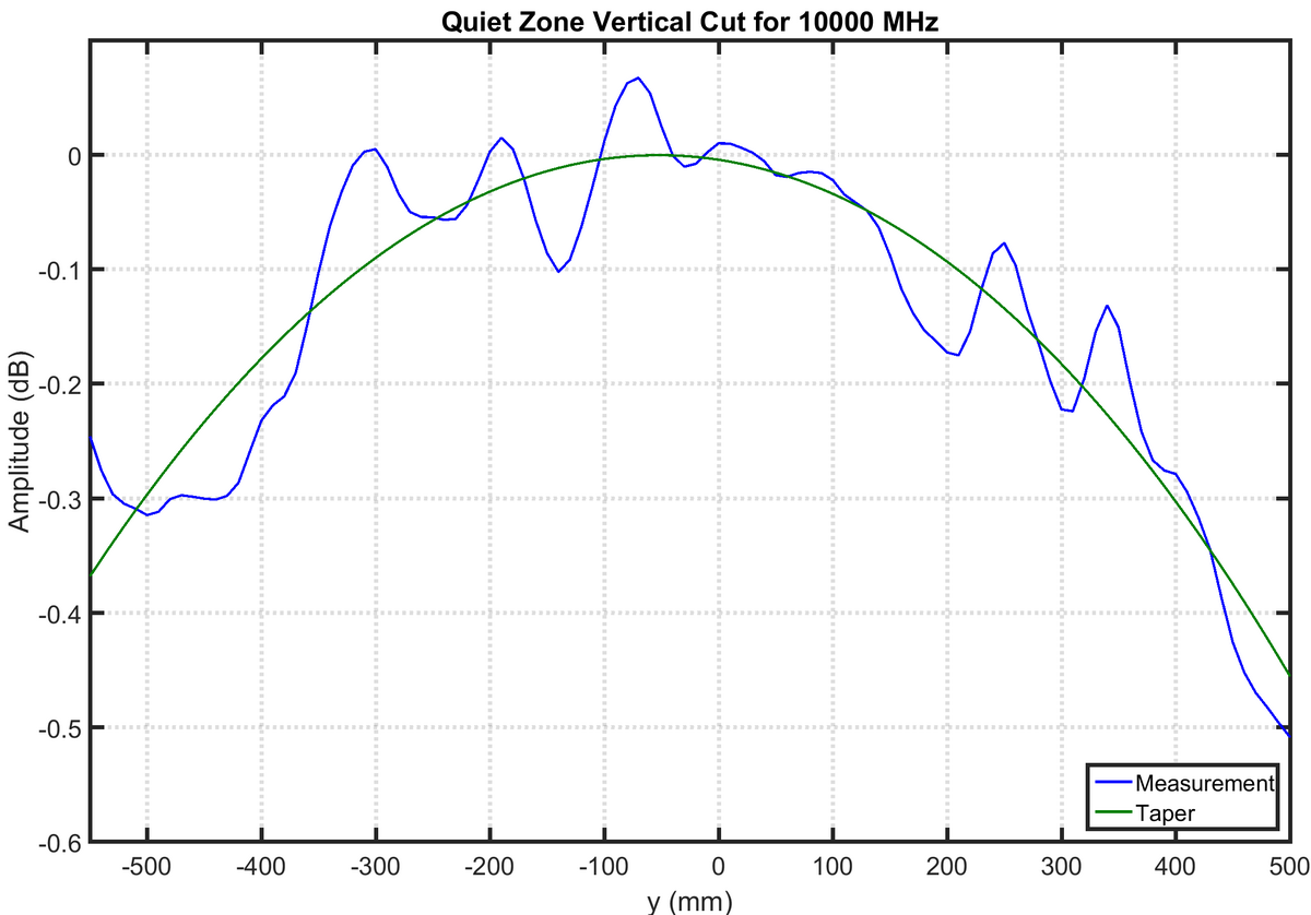
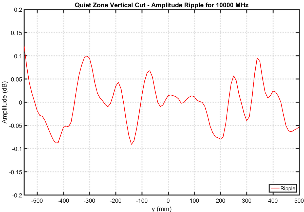
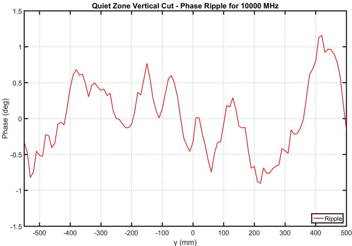
Fig. 2 shows the cross-polarization level compared to the co-polarization. A common cause for measurement errors in CATR setups using a single reflector is the high cross-polarization level. The cross-polarization level sets the minimum cross-polarization level that can be measured of an AUT. Fig. 3, 4 and 5 show the amplitude taper, ripple and phase ripple of the quiet zone at 10 GHz. As can be seen the amplitude of the ripple in the CATR of the institute is small and can be challenging to measure accurately. These measurements where conducted using the field-probing setup developed at the institute
It is quite common in chamber evaluation to not only measure the field distribution in the quiet zone transversal to the direction of the plane wave propagation, however also for a number of additional azimuthal rotations. This leads to the main pitfall of field-probing measurements, namely time consumption. Furthermore using a standard setup only single 1D cuts through the quiet zone can be measured, so further spatial information, as direction of arrival is only limited available. Lastly for low frequency bands the wall reflection can often no longer be regarded as being plane waves entering the quit zone, which deteriorates the later direction of arrival estimation.
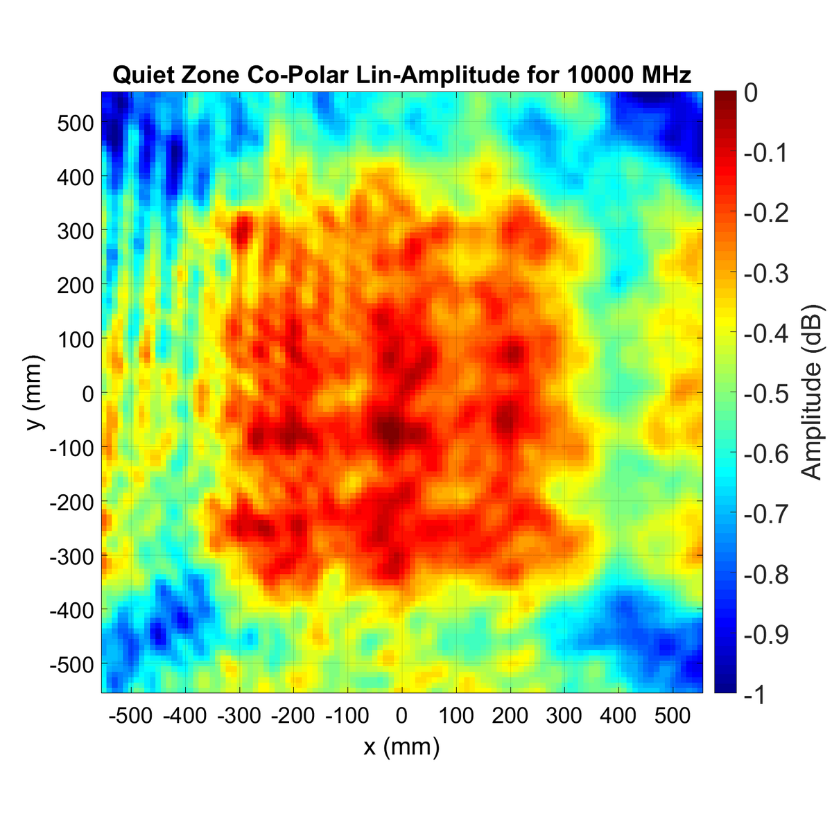
At the institute for measurements transversal to the direction of the plane wave an APC-axis is available as a second measurement axis. The APC-axis is a linear slide mounted under the azimuth-axis. Therefore for this direction it is possible to measure 2D scans of the quiet zone. Fig. 6 shows such a 2D scan.
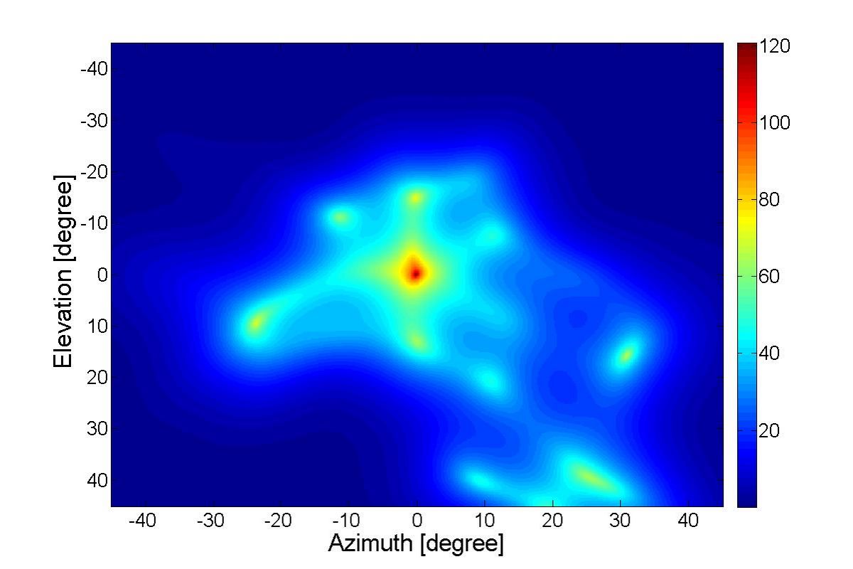
Using 2D scans of the quiet zone direction of arrival can be estimated using Multiple Signal Classification (MuSiC). Fig. 7 shows the result of the MuSiC algorithm. The output of the MuSiC algorithm in itself can only be used as a direction of arrival estimation. The signal strength in Fig. 7 only depicts the statistic independence of the signal to the background noise. In order to gain further information about the actual signal levels, as a second step signal matching and evaluation must be applied.