
Schematic Design of the Measurement Chamber
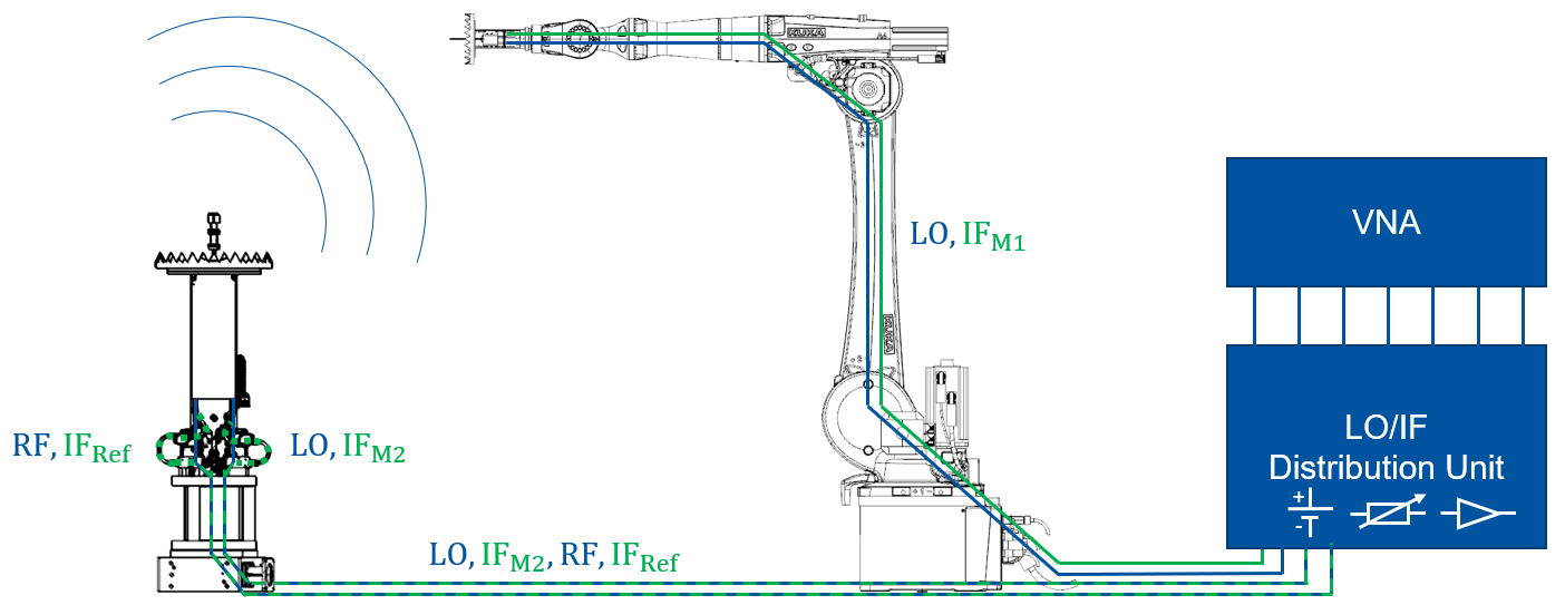
The robot-based measurement chamber of the IHF currently consists of eight automated axes, which are combined in a common kinematics and can, thus, be moved completely synchronously with each other. In addition to the industrial six-axis robotic arm, the measurement chamber provides a linear axis with another rotational axis mounted on its slide. This allows to operate the robot always in the optimal working area while reducing the risk of collisions, since the robot does not have to reach over the antenna under test.
To map the mechanical flexibility to the measurement technology, active mixer modules are used to generate the measurement signals. In this way, the setup can be easily adapted for the desired frequency range. The high frequency (RF, LO) and intermediate frequency (IF) signals required to operate the mixer modules can be conveniently reconfigured via an LO/IF distribution unit developed at IHF. In addition to a switchable power supply and programmable attenuators, the LO/IF distribution unit also offers high-frequency relays that allow to switch the signal paths. This permits to change the configuration of the mixer modules, e.g. to perform active radar measurements using the robot arm. The programmable attenuators are used to operate the vector network analyzer (VNA) in the optimum linearity range regardless of the antenna under test.
System Integration
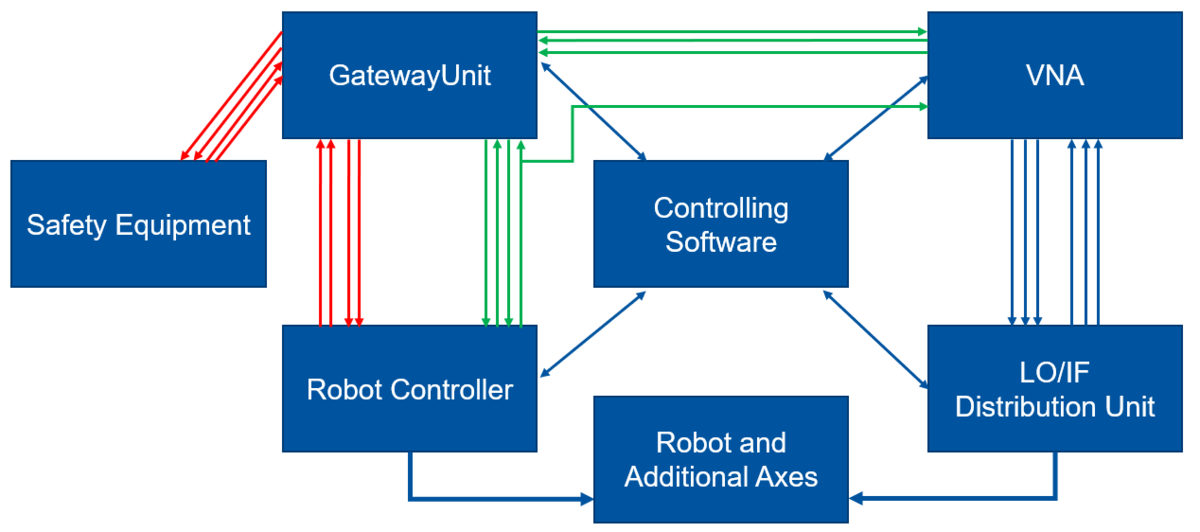
For safe operation of the robot-based measurement chamber, the overall interaction of the various components must be considered. A light fence for monitoring the endangered area is connected to the robot controller via redundant safety-relevant signals (shown in red) in order to trigger an emergency stop if necessary. The light fence has a resolution of 14mm and is, thus, able to detect even individual fingers of a hand entering the area of risk.
Temporally precise trigger signals, which are sent by the robot controller if a measurement point is reached, are enabled by a direct hardware link to the vector network analyzer (VNA), but also to the GatewayUnit. As a pedant to the control software, the GatewayUnit therefore forms the central communication interface on hardware level for linking the essential components of the measurement chamber. The GatewayUnit digitizes, processes and communicates all important information and control signals to the control software via a network connection. Therefore, the hardware unit developed at IHF incorporates both, a safety switching device with specially programmed logic and a controller for digitizing and further processing of the signal flows.